Ricon Tools
In the world of machining, understanding how to calculate speeds and feeds for boring heads is crucial. Boring operations require precise calculations to ensure the right balance between performance and tool life. Many machinists grapple with these calculations, which can impact the quality of their work. The proper speeds and feeds directly affect the cutting process, chip formation, and overall efficiency.
Mastering this skill is not just about formulas. It involves an understanding of materials, tooling, and machine capabilities. Consider the material being bored; harder materials require different settings. The size and type of the cutting tool also influence the dynamics. Constant adjustments are often necessary based on machine conditions or specific job requirements.
Even experienced machinists may find errors in their calculations. It's important to reflect on these mistakes and refine your approach. Testing and real-world applications are key in learning how to calculate speeds and feeds for boring heads. Being methodical in adjustments leads to improved results and tool longevity.
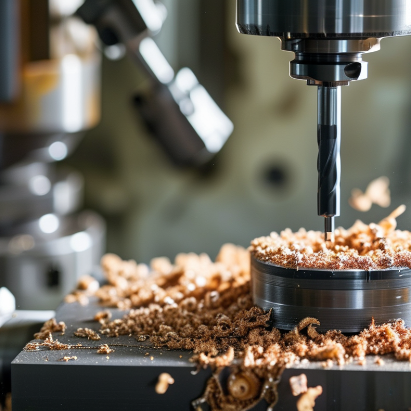
Boring heads are essential tools in machining. They allow for precise enlarging of holes in various materials. Their applications range from automotive to aerospace industries. Using boring heads effectively can significantly improve production efficiency and precision. Industry reports highlight a 15% increase in machining accuracy when using advanced boring techniques.
Understanding the mechanics behind boring heads is crucial. They operate by rotating a cutting tool within a pre-drilled hole. The ability to adjust the diameter gives operators flexibility. Studies indicate that optimized speeds and feeds can reduce cycle times by 20%. However, finding the right balance is not straightforward. Incorrect settings can lead to tool wear or even failure.
Boring head setups can be nuanced. Factors like material type and thickness affect cutting performance significantly. The complexities of these parameters often confuse operators. Some may overlook critical data, leading to suboptimal results. A focus on continuous learning and adjustment is vital for mastering the use of boring heads in machining.
When calculating speeds and feeds for boring operations, several key factors come into play. Tool material is crucial. For example, high-speed steel (HSS) may operate effectively at a lower speed compared to carbide tools, which generally require higher speeds due to their hardness. Industry standards suggest that carbide tools can run at speeds up to 300 SFM (surface feet per minute) for steel materials.
Another important factor is the diameter of the boring head. Larger diameters often necessitate slower speeds to avoid excessive wear. An increase in diameter can decrease the cutting speed. For instance, a 2-inch head might require 100 SFM, while a 4-inch head could need only 75 SFM. This relationship highlights the dependence of speed on head size.
Additionally, the depth of cut impacts feed rates. A shallow cut can allow for increased feed rates. However, deeper cuts typically require slower feeds to maintain the integrity of the boring tool and the workpiece. Neglecting these variables can lead to poor machining outcomes. All these considerations underline the complexity of optimizing speeds and feeds in boring operations. Understanding these nuances is essential for achieving the best results in any machining project.
Calculating the RPM for boring heads is essential for effective machining. Begin by identifying the diameter of the boring tool and the material being machined. This information helps in determining the optimal cutting speed. The formula to calculate RPM is straightforward: RPM = (Cutting Speed x 12) / (π x Diameter). Keeping the diameters in inches is crucial for accuracy.
When calculating, it’s important to use the correct cutting speeds for the material. For instance, soft metals like aluminum require higher RPM compared to harder materials like steel. Ensure your feed rates match the calculated RPM for better results. Adjusting these figures based on the actual conditions of your setup can lead to more effective boring.
**Tips:** Always monitor tool wear during operations. It can impact performance significantly. Consider running initial tests to validate your calculations. If vibrations occur, reevaluate your RPM and feed rate. Sometimes, less is more—slower speeds can enhance precision and tool life.
| Material Type | Boring Tool Diameter (mm) | Recommended RPM | Feed Rate (mm/rev) | Material Hardness (HRC) |
|---|---|---|---|---|
| Aluminum | 20 | 1500 | 0.1 | 0-5 |
| Steel | 25 | 800 | 0.08 | 20-25 |
| Stainless Steel | 30 | 600 | 0.06 | 25-30 |
| Cast Iron | 35 | 700 | 0.07 | 15-20 |
| Brass | 20 | 1200 | 0.1 | 0-10 |
Determining the optimal feed rate for boring operations can significantly affect productivity and tool longevity. The feed rate is the speed at which the tool engages with the workpiece material. This can be influenced by factors such as material type, tool geometry, and cutting conditions. A slower feed rate often results in better surface finish, while a higher rate may improve efficiency but lead to tool wear.
When calculating feed rates, consider the material’s properties. Harder materials typically require lower feed rates to prevent tool damage. Additionally, adjusting the feed based on the cutting depth is essential. Shallow cuts can allow for a higher feed rate, while deeper cuts necessitate a more conservative approach.
Experience is vital in this process. Operators may find that initial calculations do not yield desired outcomes. This discrepancy might result from overlooked factors like tool wear or improper setup. Regular monitoring and adjustment are crucial. Reflecting on each operation can lead to valuable insights that improve future performance. Identifying and learning from failures can transform them into an opportunity for growth in boring operations.
When calculating speeds and feeds for boring operations, common mistakes can hinder performance. One frequent error is overestimating the spindle speed. It's essential to refer to recommended surface speeds for specific materials. For example, steel may require speeds of 80-120 feet per minute (FPM) for optimal results. Ignoring material-specific data can lead to inferior finishes and increased tool wear.
Another mistake is underestimating feed rates. While slower feeds may seem safer, they can reduce productivity significantly. A well-researched report from the Manufacturing Technology Association notes that proper feeds can increase efficiency by up to 30%. It’s vital to balance speed and feed rates to avoid overheating and damaging the tool or the workpiece.
Trial and error often reveals discrepancies in calculations. Many machinists miscalculate based on incorrect formulas or outdated guidelines. Constantly reevaluating your approach is essential. Utilizing software tools can streamline calculations and help visualize the process. Experience plays a crucial role, but relying solely on it without considering updated data can be detrimental. Factors such as machine rigidity, coolant usage, and tooling conditions should always be factored into calculations to ensure reliable outcomes.
: Boring heads are tools for enlarging holes with precision in various materials. They improve production efficiency.
They rotate a cutting tool inside a pre-drilled hole. The operator can adjust the diameter for flexibility.
Advanced techniques can increase accuracy by 15%. Speed and feed adjustments are important for optimal results.
RPM affects the machining process. Incorrect RPM can lead to tool wear or machining failure.
Use the formula: RPM = (Cutting Speed x 12) / (π x Diameter). Ensure diameters are in inches.
Tool material, diameter of the head, and the depth of cut all affect speeds and feeds significantly.
Softer metals require higher RPM, while harder materials, like steel, need lower RPM for effective machining.
Always monitor tool wear. Excessive wear affects performance and may signal the need for adjustments.
Some overlook critical data, like material thickness. This can lead to suboptimal results and ineffective boring.
Focus on continuous learning and adjustment. Running tests can help validate calculations and optimize settings.
In the realm of machining, understanding how to calculate speeds and feeds for boring heads is essential for achieving optimal performance and efficiency. The article delves into the fundamentals of boring heads and their applications, emphasizing the key factors that influence speeds and feeds during boring operations. It outlines a step-by-step process to accurately calculate the RPM necessary for different materials and conditions and provides guidance on determining the optimal feed rate for effective boring.
Additionally, the article highlights common mistakes that machinists may encounter while calculating these parameters, ensuring that readers are well-equipped to avoid pitfalls that could affect their machining processes. By mastering these calculations, operators can enhance their productivity and ensure the best outcomes in their boring tasks.
